MATERIALS HANDLING.
HDPE virgin
HDPE will absorb less than 0.01% water in 24 hours at room temperature. This means that drying is not normally necessary. If it is, dry in a hot air oven for 3 hours at 65 C. HDPE is available in both granular and powder form. The powder form is cheaper but can give problems of materials handling and feeding. The granular form is much easier to handle as it will flow under its own weight but can create problems if it is blended with masterbatch as separation can occur in the machine hopper.
FLOW CHARACTERISTICS
Because the impact resistance of HDPE decreases and notch sensitivity increases as molecular weight falls the most commonly used grades of HDPE have high molecular weights i.e. low values of melt flow index (MFI). Using the traditional 2.16 Kg weight at 190 C, HDPE extrusion grades all have values below 0.3. To enable these grades to be more readily distinguished, the MFI test is carried out with a 5 Kg weight giving values about 3 times greater than those found with the 2.16 Kg weight. Note
that the MFI values at 5 Kg are higher than we would expect from the change in weight because of the viscoelastic properties of polymer melts. For film MFI (5) values in the range 0.17 to 0.53 are used while for sheet and pipe typical values are about 0.4 and for cable sheathing about 0.85. The viscosity for a typical pipe grade with MFI (5) = 0.43 is given by;
Viscosity = antilog ( 4.866 - 0.0030 x temperature (C) - 0.538 log ( shear rate (s-1)))
SCREW AND BARREL DESIGN
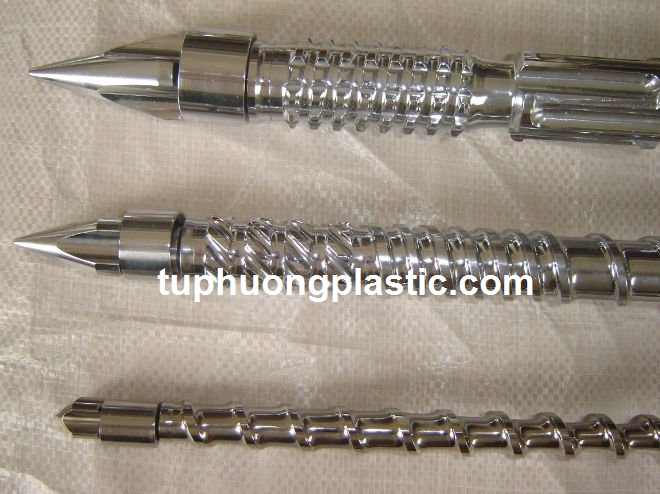
Metering 8D. Zone depths in mm are given in the following table.
SCREW (mm) FEED ZONE 1st METERING 2nd METERING
63 9.3 3.6 6.0
90 11.4 4.7 7.5
115 13.1 5.6 8.6
150 15.6 6.8 10.6
Barrier type screw designs have also been used successfully with HDPE. Typically a 115 mm barrier screw will have a 24:1 L/D ratio and be operated at up to 100 r.p.m. If grooved feed inserts are used in the barrel they should be cooled and the grooves fine. For a 63 mm extruder, there are 8 grooves each of depth 2.5 mm and width 8 mm. The grooves extend 3.5 D beyond the feed throat opening. With a grooved feed section longer screws incorporating shear and mixing sections are recommended.
BARREL AND DIE TEMPERATURES

Temperature controller
Since melt temperature depends on screw design, screw speed as well as barrel and die settings the following table is a guide only.
APPLICATION Sheet Film Pipe
MFI (5) 0.6 0.17 0.53 0.43
Zone 1 temperature 185 190 190 190
Zone 2 temperature 195 230 200 205
Zone 3 temperature 210 250 220 215
Die temperature 210 250 220 215
DIE DESIGN AND CONSTRUCTION
For smaller pipes spider type dies are generally used. For large pipes, a spiral mandrel is used or the conventional mandrel is held in place by a breaker plate type support. The land length should be 14 to 25 times the pipe diameter, the greater the output velocity the greater the necessary land length. Blown film dies are of the spider type with a smear restriction downstream of the spider supports or of the spiral mandrel type. Typically, the die gap is between 0.75 and 1.40 mm and
the die diameter between 75 and 200 mm. Sheet dies of the type used for HIPS are satisfactory. Sheet thickness of up to 12 mm is possible. The die should have an adjustable land after the rnanifold and choker bar sections. Land lengths of 65 mm have proved satisfactory.
DOWNSTREAM EQUIPMENT
Both pressure and vacuum sizing are used for pipe production. For pressure sizing, there is a slight expansion after the die i.e. the die gap OD equals the pipe ID. For vacuum sizing the expansion is greater with a 25% increase in diameter common. In blown film, in order to achieve reasonable impact values a relatively large blow up ratio between 3 and 6 is employed. The bubble has a long neck (between 6 and 9 times the die diameter ) and a characteristic wine glass shape. To achieve greater stability with this shape of bubble an internal stabilizer can be used together with an outer 'iris diaphragm'. In these cases
the bubble often contracts to a diameter less than that of the die opening before eventually expanding to the final film diameter. Sheet is extruded onto a polishing roll stack consisting of 3 to 5 polished, chrome plated rolls of at least 200 mm diameter. The gap between polishing rolls is often about half of the die gap or slightly more for the higher melt index resins. The table below shows roll temperatures in centigrade. The temperatures refer to the circulating fluid set points. Surface temperatures will be less until the extrudate is being cooled.
ROLL Top Middle Bottom Fourth Fifth
TEMPERATURE 99 110 107 88 66
EXTRUDER PLASTICIZING CAPACITY
Line capacity depends on both the extruder, the die and the cooling section. The table below shows some typical outputs in Kg/hour.
EXTRUDER SIZE APPLICATION
Blown Film Thin Sheet Thick Sheet
(< 0.1 mm) (6 mm)
30 50
63 170 150 100
90 300 290 190
115 520 340
150 1,000 680
STARTING UP
There are no special problems with HDPE. Follow the procedures laid down for LDPE taking special care not to melt the polymer in the feed section before extrusion starts by keeping temperatures low until just before the screw is started.
SHUTTING DOWN
Three are no special problems though for die and extruder cleaning it is helpful to purge with LDPE. To prevent oxidation, leave polymer in the extrusion equipment and reduce temperatures as fast as possible when it is intended to start again at a later date without cleaning the equipment in the intervening period.
REPROCESSING
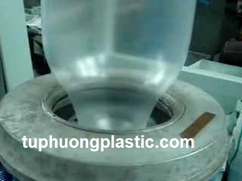
Blowing film
When this material is reclaimed it is suggested that up to 20 % may be blended into the virgin Material.
FINISHING. This material may not be joined to itself using solvents as there is no solvent at room
temperature. Because of its inert, 'non-stick' surface it also cannot be very successfully bonded using adhesives, limited success with contact or hot melt adhesives. If the surface is made polar, for example by using a flame or an electrical discharge, then this material may be bonded to metals using epoxides or nitrile-phenolic adhesives. Corona discharge treatment is necessary before printing on HDPE. HDPE is commonly welded using techniques such as hot plate or hot shoe.
Machining of this plastic is difficult because of its soft, resilient nature. Do not apply too much pressure when machining as the material will distort.
-
Tel: (84)-243-652-4915
Email: info@tuphuongplastic.com